Tuesday, January 29, 2008

Aitor Throup


Just in case there was any question about whether fashion is (or can be) art or if it's just some handbag with a logo repeated 1000 times...


Aitor Throup is an English designer fresh out of school and already making some incredible art. The picture below contains part of an article about his collection "The Funeral of New Orleans." The collection tells the story of 5 musicians in New Orleans trying to survive Katrina and ultimately sacrificing themselves to save their instruments. It's pretty amazing.

I highly encourage you to go watch the video (make sure your sound is on!) of the outfits of the five musicians transforming from protection of self to protection of the instrument.

Good Sky at the Velodrome


Encino Velodrome on one of the open track days. Great clouds great day.


The great clouds turned even greater as the sun set. The photo doesn't do it justice though. The sky was more red than the light pink.


Motobecane Champion Team track bike in the sunset. I did get a little bit of riding in when I wasn't in "dude, the sky is amazing!" mode. Yes I was that guy and no I'm not proud of it.

Opossum Touching


This guy was on my porch.


And I touched his tail. I touched his back too but then he made bitey face.

Carrying Heavy or Awkward Stuff Home on your Back/Bike


Don't think you need to borrow a car (or drive your car if you own one) to go pick up a vacuum cleaner or some lumber. All you need is a roll of packing tape, strong legs, good balance, and a good back. I always keep a roll of packing tape in my bag just in case. My latest heavy transport was an office chair from work.


Here is a full sized upright vacuum and a paper shredder that came home from Target.


This came from a lumber run I made to Home Depot. This was probably the trickiest because the ends of the board would start vibrating and oscillating when I rode which made balancing very tricky.

Shaping Lugs and a Track Crown with Brass


These are details from a bike I made a couple years ago but never got around to sharing. I wanted to give a larger radius to the joints of the Henry James lugs so I filled them with brass and then silver brazed the bike together.


This first picture is the top tube/head tube lug filled with brass and with a head tube extension added to give a more comfortable bar height while riding. I talked to Tom Kellogg at NAHBS #2 about extending the head tube which I have seen on his bikes and mentioned that Spectrum had started by using Henry James lugs and brass brazing an extension on, but this would end up cracking eventually at that junction. Then they tried tig welding the junction but with the same results. The solution that they came up with to avoid the cracking at the junction of the lug and the extension was to have their own lugs made with the extension already built it. No more cracks.

PS- By crack I don't mean doom crack. I think what Tom was saying was that the junction was just a flexy point and the two lug pieces would come unattached to each other but would stay in place due to being brazed to the head tube. The head tube remained intact.


Here is the seat tube lug with the same effect. The cap on the seat stay was made my filing the tops of the seat stays to accomodate a small piece of 1" tubing and then brass brazing them together. Then the whole thing would be silver brazed to the seat tube cluster. It comes out lighter than a braze in solid steel cap, and you can use whatever diameter tubing you want as the cap for different effects.


And again...


And again...


I also filled in an Everest track crown to have a totally new look. The Long Shen track crown that takes the 24mm round blades is pretty much the same design if you are familiar with that. This was a pain and a waste of about 500psi of oxygen but kinda cool. Wouldn't do it again.


You can see that the normal concavities that exist between the fork blade zone and the steerer tube zone have been filled in to give the crown a more oval shape when viewed from the top. I also did away with the pointies on the outside of the crown and made a flat area with a small slot remaining.


Here is a picture of the original from the Nova site.

Sunday, January 27, 2008

Fireplace Screen


This is a fireplace screen that I designed and built for my friends Melanie and Dave's new house. This was a long project because I work slow and I'd never done anything like this before. I kept having to stop and find solutions to problems I didn't even know existed until I ran into them.


Here is the money shot. Below you'll find a description and more pictures than you ever wanted to see of this thing being built.


Here it is with it's doors open. I designed it with the thought that if I kept the upper edge straight and made the bottom curved I would get an interesting surface out of the screen, which happened for the most part. I originally conceived of something a little more wiggly where the doors come together instead of a straight line but the screen material would have had to have been much more flexible and the hexagon pattern was well loved by all so we decided that this was the best thing to do.

The doors fit very snugly into the frame, so much so that they won't stay all the way closed unless you hole them closed somehow. While I thought this was a problem at first I realized that it was actually going to work out well. Either you have doors that want to stay closed and you need a way to open them, or you have doors that want to be open and you need to find a way to keep them closed. Since my doors wanted very much to be a little bit open all I had to do was make a simple latch at the top of the firescreen to hold them closed. This enabled me to skip handles or other opening devices entirely and maintain a clean, smooth surface on the piece. Just pull on the little latch and the doors pop open by themselves enough to get your fingers in and open them the rest of the way. Thankfully the doors stay cool enough to allow this to work without burnt fingers.


The entire screen is made of 1/2" steel angle iron and 3/8" square steel tubing. The bottom part of the frame is the first bend I had to make. It was bent by hand using the vice to secure it.


Here is the base of the frame being welded to the vertical pieces. Originally I had intended to have the vertical pieces twist, which would allow for no gap at the connection point. The vertical pieces of the doors would twist to match but I realized that the hinges would be off center from each other if the frame twisted making the door unable to open.


After giving up on the fun twisting idea, I patched the gap by welding some scrap metal to the joint. This is looking at frame from the bottom.


With the frame completed, it was time to start bending what would become the bottom of the doors. This piece was bent by hand in the vice just like the bottom of the frame. It took a while to get the bends to match but it turned out well.


Now the outside borders of the door were complete. The next step is putting in the upright sections where the doors will join in the center.


Here is the frame with the outside borders of the doors nested inside of it.


In order to get the vertical sections in the center of the door I had to figure out exactly where to cut the door piece in two. Finding center on the top was easy but the bottom required a T-square on the center point of the top that was extended down by some more measury stuff.


Saw saw saw saw saw...


After the cut was made to separate the door the two vertical pieces were cut and fitted to the doors while they were in the frame to make sure they would remain the right shape and size.


At this point I got the first look at the interesting shapes the firescreen makes when the doors are open. Going with the straight top and curved bottom worked out well and I was glad I didn't go the WDCH wiggle route. Unfortunately once the hexagon mesh was put on the effect wasn't quite as striking, but no mesh, no fire prevention goodness.


Here are the doors complete with the mesh brazed on. The screen is finished except for hinges and whatever handles will be attached. Originally my thought was that the mesh would be riveted on. When it came time to do it however I thought about the little bumps that would be all over the place and decided that silver brazing the mesh all the way around the perimeter would give the door the clean look I wanted it to have. It was a lot of work and the screen is fairly delicate so I came pretty close to melting it in a couple places but in the end it was the best way to do it.


The first hinge is being fit to the door. One of the problems I ran into was how to attach the hinge to the door when the door frame was buried beneath the screen. I thought about this a lot but ultimately it didn't need much thought because there was only one thing I could do. I sliced a little hole through the screen just big enough to pass the hinge though. The screen is still enough so that it kept it's shape just fine. Here I have the hinge held in place with a clamp and a piece of the 1/2" angle iron attached to create the correct space for the frame when the doors are attached to the frame.


A close up of the hinge welded in place and how it is passing through the screen. There are two hinges on each door.


Here is one of the doors with both hinges welded on. This one is ready to be attached to the frame.


Here's the setup for welding the door to the frame. I had to clamp the doors together and to the frame in the top center because the fit was very tight and they kept wanting to pop open. I needed the doors to be held in place just like they would be when closed later so the hinges would be welded on in the correct position.


I'm not sure why I decided to weld the hinges on to both the door and the frame. If they wear out they are going to be a pain to replace. The hinges have removable pins at least so the doors can be separated from the frame if need be. I think I didn't rivet them because access to the hinge attach point was very limited due to the screen being in place so I just had to sneak the TIG welder in as best I could.

Upright Internally Geared Bike for Dad


My latest bike is based on the design of my commuter but built for use with a Shimano Nexus 8 internally geared hub. My dad used the Look stem until he found a comfortable position that didn't bother his neck. I've since made him a stem to match the way the Look stem was set up. The integrated rack on the back was unfinished at this point because I needed to see if the seat height would accommodate the bag fitting part way beneath it or if it would have to sit behind the seat entirely.


Here is a close up of the fastback seat stays. All the TIG welding I've done so far has been without the pulse function on. Now I am trying to figure out the pulser. It's taking a little getting used to. Update: I gave up on the pulser.


Here is the finished stem.

Stool For The Old Man


Here is a stool I built for my father. Another TIG practice project. That fine, fine wood you see is 2x10 I found in the alley and stained.

Saturday, August 11, 2007

First Tig Welded Bike


I've been picking up tig welding. I started by doing around 200 practice welds (1 or 1 1/8" welded to 1 1/4" at a 73 degree angle, approximating a top tube to a head tube) before I tried to build a bike with it.


Here's a picture of my first (tig'd) bike. This is my daily commuter/fixed gear.


With integrated rack


The rack was added later as evidenced by the rust/no rust finish. I'd had enough of the messenger bag sweatback.


Here's the bike after I finally had it powder coated off-white. I originally had planned to leave it raw metal because I figured it would only be a summer bike and the rust wouldn't be a big deal. However, when I tried to get back on the rain commuter bike I had ridden before this bike I hated it and got this one powder coated so I could ride it year round.


Here is what some of the many practice weld pieces became. Night lights!

Thursday, May 18, 2006

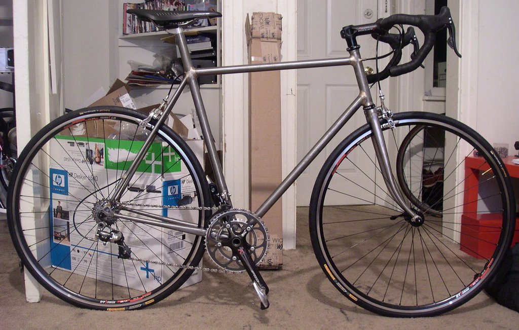
Internally Routed Road Bike


I just finished my first and what will probably be my most extreme internal routing project. I'm going to do it again and incorporate the good ideas and excorporate the dumb ones and make a really cool internal setup. Did a couple of things to make this work:

1) Bruce gordon/high end Time frame non or less adjustable seat post setup that raises the binder bolt up and uses a long seat tube. No seat tube passing through the seat cluster so i could route cable through there

2) used 1/8" stainless tubing with an ID of .020 (I think, whatever it was it was big enough for brake and der. cable alike without too much drag. works well) and fully routed the inside of the bike.

Like I said, some of the ideas are cool and some are forehead smacking dumb. This was my first road bike build (my fifth frame, all the rest were track and didn't need braze ons) and my first time fillet brazing a frame.


There she is. One painted with the routing fixed and one raw with it still messed up.


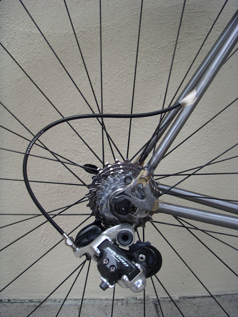
The rear derailleur cable routing goes through the top tube, goes through the seat tube, into the right seatstay and pops out above the rear derailleur about 2/3's of the way down the seatstay. Once cable is routed through and the chain is on the der. will be pulled down a bit and the housing won't be so long and loopy looking.


Rear brake goes through the top tube along side the rear derailleur housing but pops out of the rear of the seattube right behind where the top tube ends. I wanted it to pop out the seatstay like the rear derailleur routing did but it wouldn't leave enough cable to allow the lengthening of the cable when the brake was applied. Once the cable is routed the brakes will be tighter (they are all the way open now) and the curve in the cable housing in back won't be so pronounced.


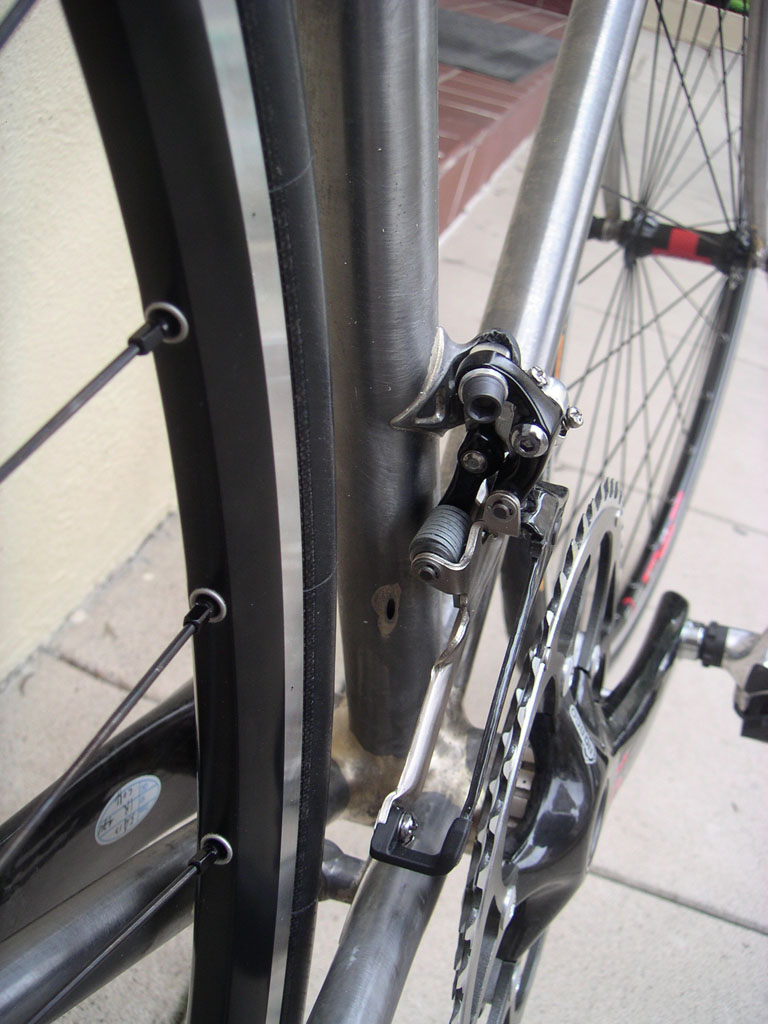
Front derailleur cable routing goes down the down tube, curves around and pops out travelling upward on the seat tube maybe 3 inches below the derailleur bolt. Travels totally internally because the stainless housing bends and travels above where the actual bottom bracket sits in the shell where the seat tube and down tube meet. There is space there to route the housing and the curve is more gentle than winding around the bb shell on the bottom as usual. Sorry no cable running through it to show it better. I will add finished pictures but figured I should jump on this before everyone is so totally over talking about internal routing.


UPDATE: This has been fixed, but I'll include the dumb first way and then show the fix.

All the cables enter through the headtube, slide by the steerer tube, and enter the top tube or down tube already inside them. Internal routing starts at the rear of the headtube flush with the inside of the headtube. That was the dumbest idea. I had to use a derailleur cable for the rear brake cable as normal brake cable was too thick/not flexible enough to move around the head tube. Also, even after two rides there are little notches being rubbed in the steerer tube. I also can't ride no handed unless I'm going pretty fast as the steering is too stiff and doesn't correct itself easily enough. I'll have to try and fix this by pulling the internal routing out to the sides of the top tube if I want to keep riding this bike. Would have been the same effect to have barrel adjusters on the side of the headtube and have the cables enter close to the headtube on the bottom side of the top tube and downtube. Would have looked almost the same without a ton of hassle and you'd be able to use a carbon fork. I planned on using gore-tex or teflon cables to ease the drag and possible wear from rubbing factor on the steerer tube, but still, awful idea.


Here is the fix. I had to drill holes in the sides of the tubes, drill through the internal routing to separate it from the head tube (it was brazed where it went through the headtube), and then fish the length out of the sides of the top tube. At that point I modified some water bottle bosses to receive the housing and drilled a tiny hole in the closed end to accept the 1/8" stainless internal housing. Once I passed the stainless through the water bottle bosses I was able to lay them over in the frame how you would normally do internal routing and braze them in place. Only problem was that I wasn't able to braze the stainless to the water bottle bosses because that was inside the frame. The problem worked itself out when I drilled into the water bottle bosses to get rid of the excess stainless housing. When I had removed the excess stainless the end of it looked like a rivet does after it's been set. The end was widened and would not pull through the boss.

The 4 plates you see brazed on the front were quick patches for the holes that were in the head tube after I took the routing pieces off. I decided to leave it really rough and I actually like the results. A cool headbadge.


Here is the seat tube with brazed in internal housing for the rear brake and rear derailleur cables.


So real quick, the order of operations of the tricky stuff:

1) From the pics you can see that I brazed the two s.s. routings to the seat tube first after I had gotten their bends correct.

2) Once seat tube was in jig I brazed the front der. routing to the seat tube where it comes out.

3) Then I slid on the top tube and down tube on and if you route it like it should be done your cables will pop out towards the front of those tubes. I'll skip the excessive complications of routing through the headtube like I did.

4) Put the seatstays on and made sure it popped out the bottom where I wanted it.

5) I tacked the whole thing at once and brazed the whole thing in one shot afterwords. No front triangle then rear triangle. The only part I had assembled already was the chainstay/dropout/seatstay assembly. Then did all the rest.